The Digital Clock DC-002 project took more than a year to build(1) and was a project of many firsts for me. In addition to being my first SMD project, it was the first of which I built multiple units, the first to include a nice enclosure, the first with packaging, and the first with an extensive user manual. What is most important to me about the DC-002 and it's predecessor DC-001, was that I built them exclusively as gifts for my close friends and family. This is the story of design, development, and construction.
Note: I initially wrote much of this article shortly after building these clocks, but completed the sections after the Surface Mount and Assembly section more recently from contemporaneous notes. A number of footnotes have been added prior to publication (in December 2022) with updates.
DC-001
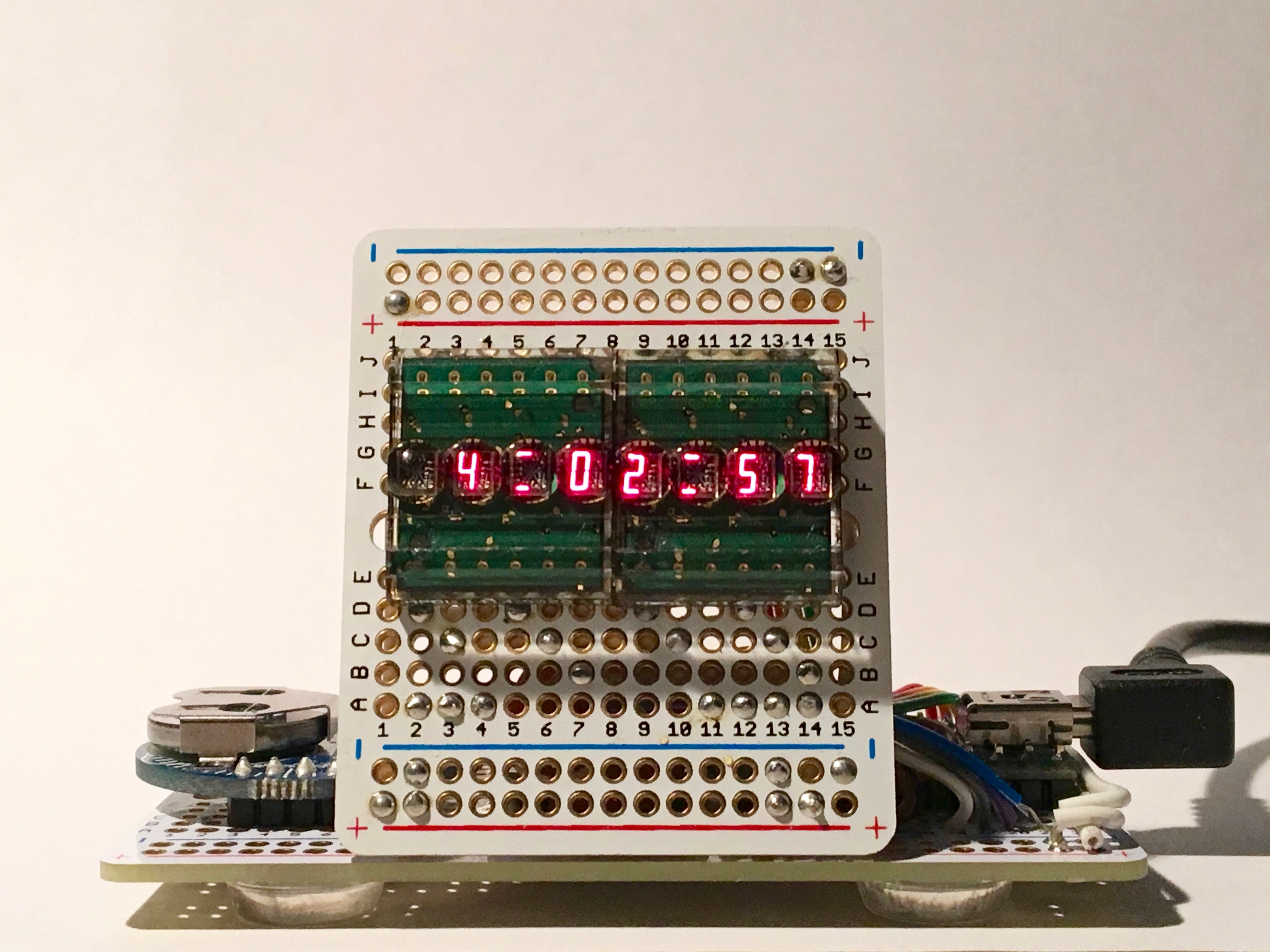
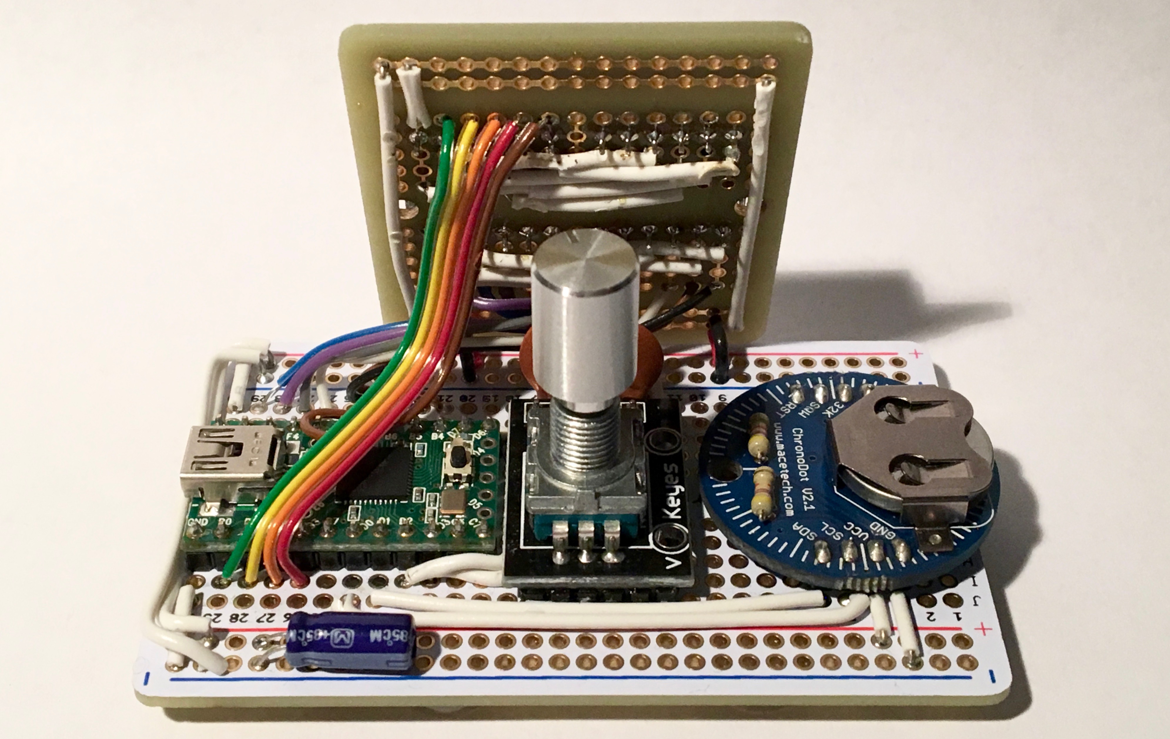
In October, 2015 I started tinkering with the idea of building a digital clock using some HPDL-1414 bubble displays that I had acquired after seeing a post on Hackaday. In the summer of 2015 I had taken a road trip to Denver, CO and visited my dear friends Mara and Scott. I wanted to make them something nice for Christmas, so by December I built DC-001. This clock used a Teensy 2.0 from PJRC, and a Chronodot for timekeeping. Assembled primarily with Adafruit Perma-Proto boards, the style was certainly function over form. Aesthetically polarizing might be a generous way to characterize the design. I did my best to use the Boldport soldering style to make it look nice though. Quite a bit of work went into the software around this time. In an effort to make it feel like a real product, DC-001 was delivered with a complete user manual.
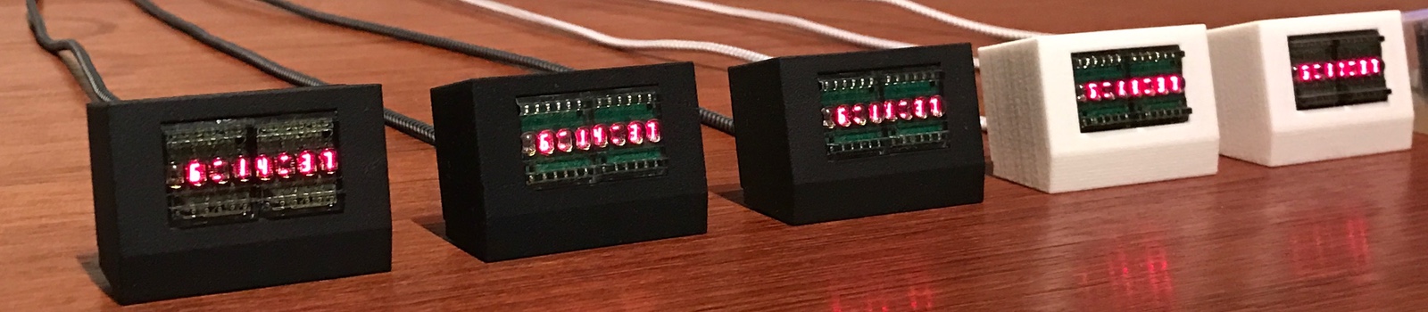
As soon as I had finished with DC-001, I knew I could produce something that felt more like a real product and began work on DC-002. The project was shaped by a clear set of ideals I had in mind at the outset. Goals included surface mount construction, a proper enclosure, and improved ergonomics. Intentionally, I did not try to design for manufacturing, build an actual salable product, or optimize the BOM/assembly costs. I also knew I wanted to document the project and provide sourcecode for others to examine, make something fun and inspirational, learn some things, and build a good gift. I did not know at the time it would take me a year to build 8 units.
DC-002 Circuit Design and Layout
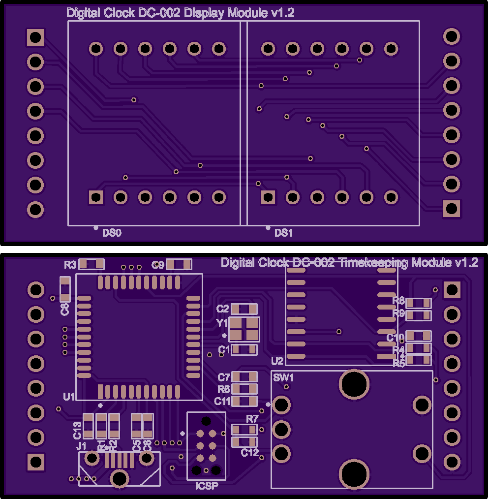
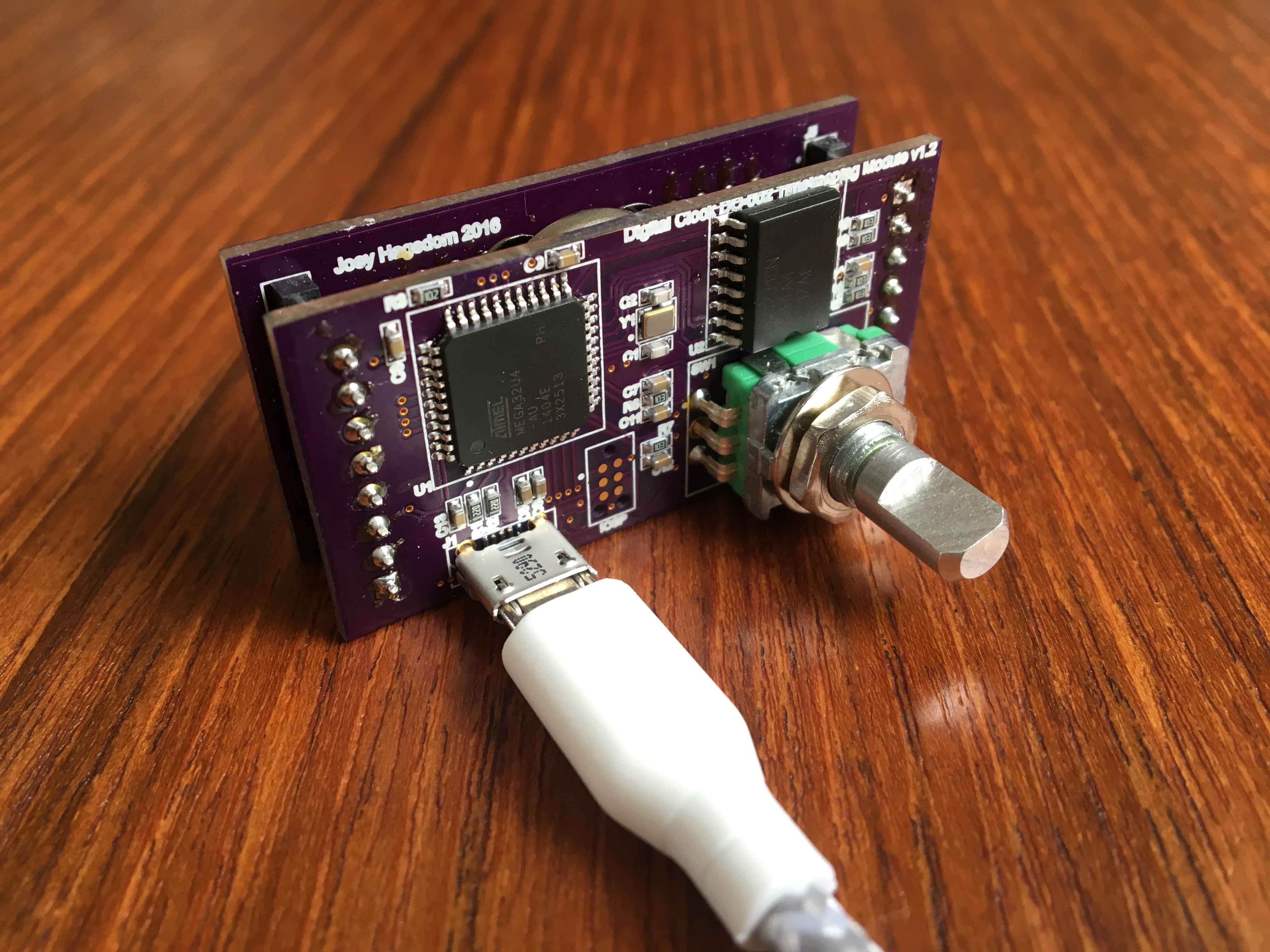
I discovered Upverter(2) and began the PCB layout process. It was a welcome change from Eagle, but the pricing structure is weird and I still run in to a number of bugs; more on that later. I am indebted to PJRC regarding the circuitry; I started the layout process from the Teensy 2.0 reference design, and added the DS3231 and accessories to make it work. I was enthusiastic about the sandwich construction so I could keep the face of the clock as small as possible, so I moved forward with a 2-PCB design. I know it cost a little bit more to manufacture, but I’m happy with the final dimensions.
I encountered a few issues with the PCB in the design phase, specifically some trouble making the pours for the ground plane on Upverter, but they were helpful and addressed these issues in the tool. Some of it came from that attempt to optimize the 2-PCB layout in a single document so I make a single order from OSHPark.
By the end of January I had received the first batch of parts and PCBs. The first run of PCBs had some severe defects. It would be easy to blame this on lack of attention to detail, but I suspect I just needed to learn some of these lessons from experience. First, I failed to follow the guidelines for slots/holes from OSHPark and the mounting holes for the rotary encoder and usb connector weren't drilled. This was easy enough to workaround with a pair of wire cutters, but unfortunately the first revision of the board had more significant problems. The backup battery was shorted between +3.3V and GND because I had missed removing the copper pour when removing the soldermask, making it useless. I wanted a nicer footprint for the battery holder than the stock one provided and paid the price. I noticed this before I received the boards, but after the order, so I put in an order for a second revision before even getting the first. This second revision had the slot cutting error—so anyway I ended up with a bunch of great FR-4 shims before finally getting the 3rd order right.
One issue I failed to resolve until it was too late was blurry text on the silkscreen. All of the production units still had blurry silkscreen, though I’ve fixed it since if you'd like to make your own. I appreciate the help from Laen at OSHPark in resolving this; the problem appears to more recently have been fixed in Upverter, described in this thread.
Parts and… Counterfeits?!
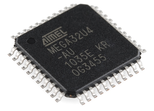
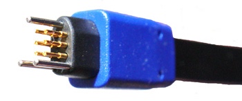
Most parts for the DC-002 were procured new from online distributors such as Digi-Key. I choose to purchase the ATMEGA32U4 pre-programmed with the halfkay bootloader directly from PJRC so the project could be constructed and programmed without a hardware programmer. Eventually, in later revisions of the PCB design I found room for an ICSP port via a Tag-Connect 6-pin footprint.
While I had no problem selecting excellent parts from Digi-Key, I definitely had a bias toward more expensive but interesting components. While lower cost substitutions could be made, that wasn't necessary here because of the very limited production run and the fun that came from using overkill components like the DS3231. Suppliers and component details are documented in the BOM.
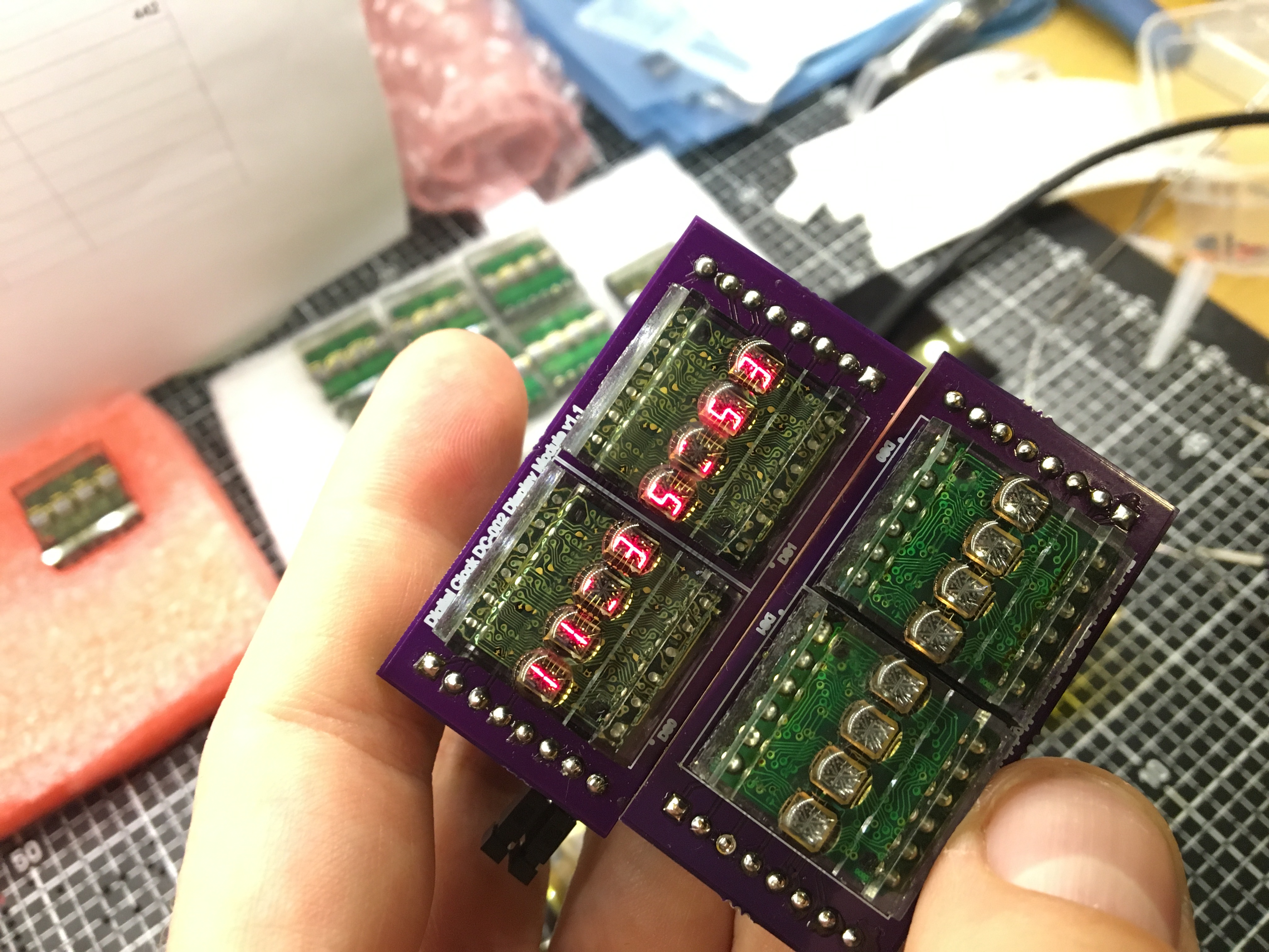
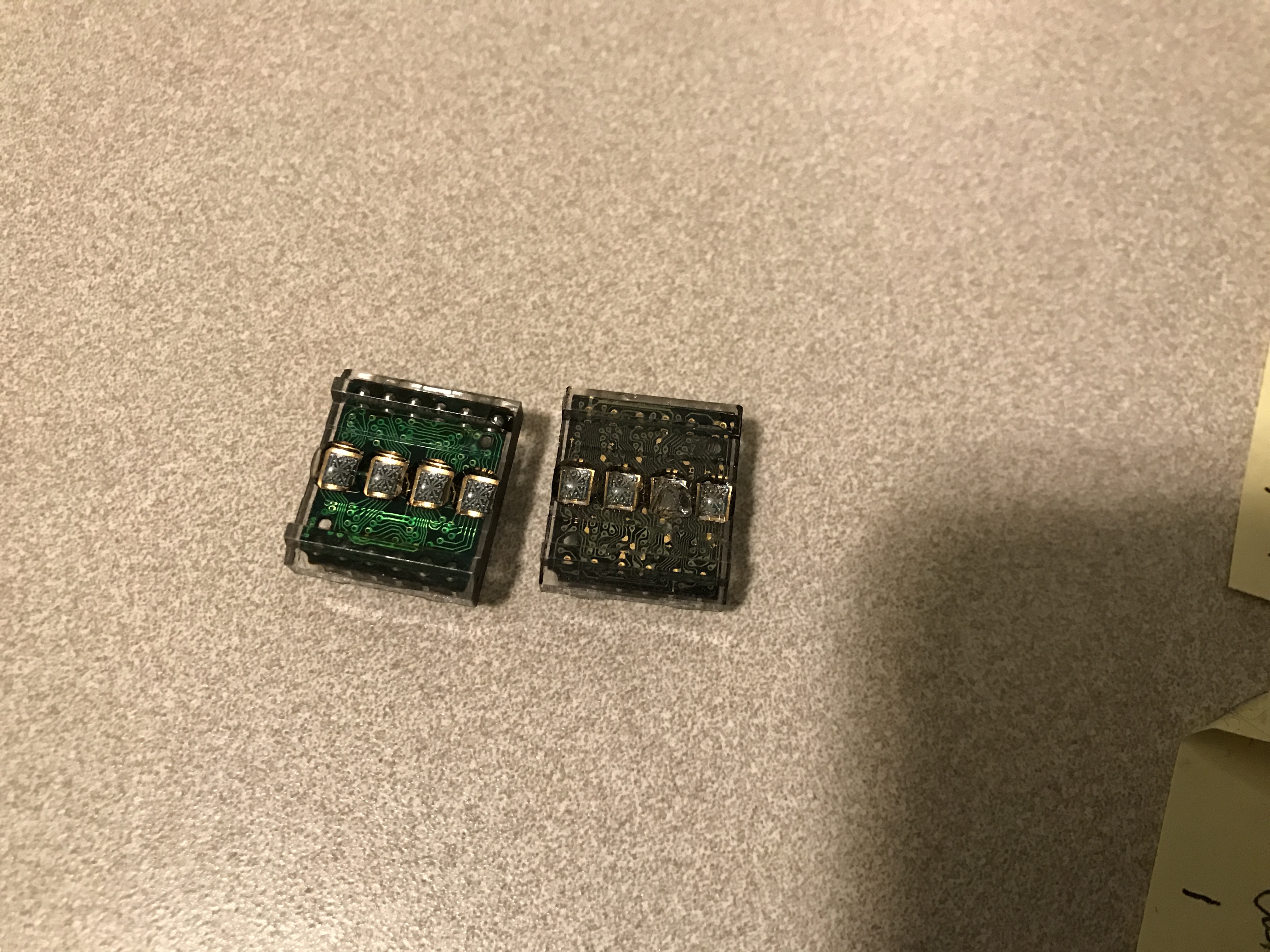
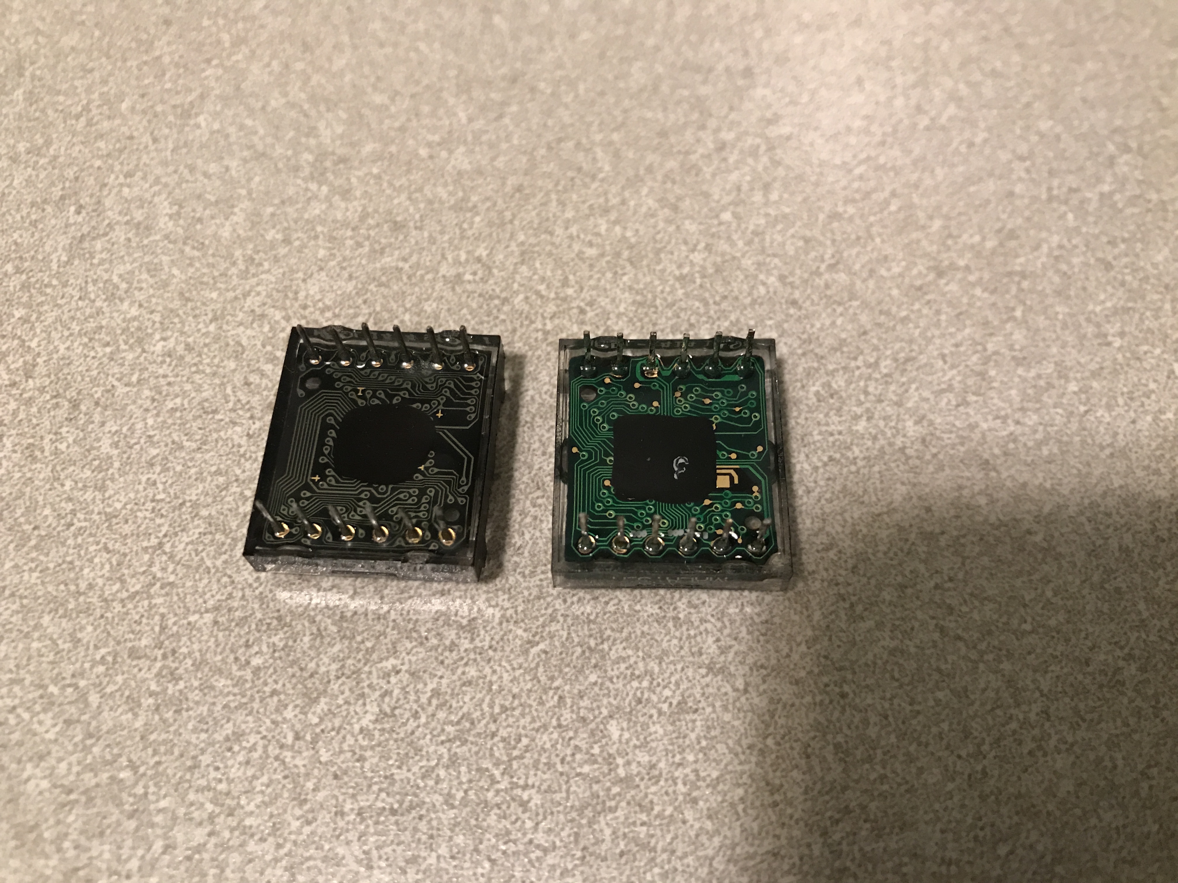
One part I couldn’t get from Digi-Key was the HPDL-1414 bubble display. They’ve been obsolete for longer than I’ve been building electronics, and in this case were supplied from utsource.net. While I very much appreciate the availability of parts at a low cost, I was nonetheless disappointed when I received what I suspect are counterfeit units in my second order. I paid only $2.33/ea, so it wasn't a huge loss, but frustrating not to have a reliable supplier for the marquee component of the project.
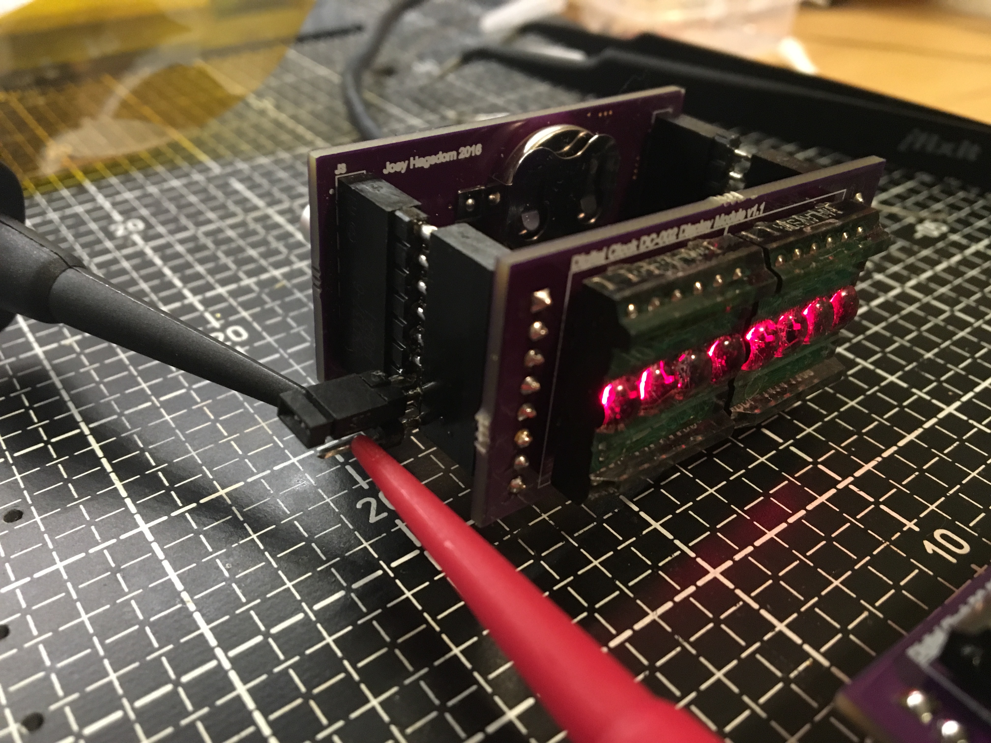
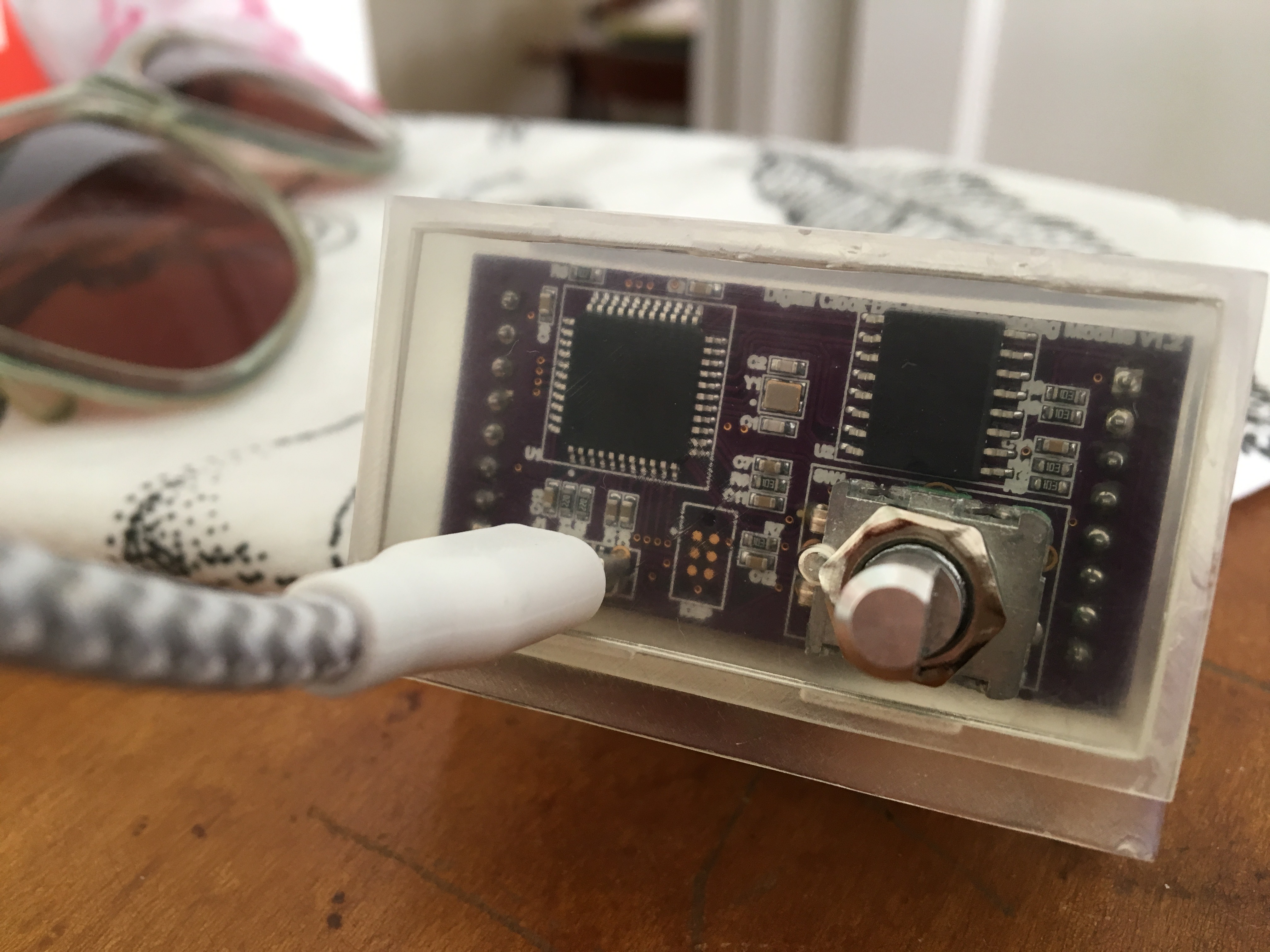
The visual appearance of these displays was different than my first batch, so I did some testing. I built a test rig to measure current to the display board via a jumper and compared consumption between the genuine and suspect counterfeit units. The counterfeits ended up using more power, which leads me to believe this was not simply a cost-reduction process change in later manufacturing runs but indeed fakes. My suspicions were further confirmed when I discovered some units appeared not to have the HP logo molded into the front lens, but instead a blank circle.
| Module | Power Consumption |
|---|---|
| Genuine HP | 73.2mA |
| Counterfeit | 82.2mA |
| % difference | 12% |
Surface Mount and Assembly
I had never worked on a SMD board before, but decided to go for 0603 size components as they seemed as if they’d be manageable for hand soldering and really reduce the final size of the project. I knew I wanted to produce several identical units, but also wanted the ability to rework boards, so invested in a Hakko 850 from eBay instead of a reflow oven(3). This made it easy to fix assembly errors, but was certainly the more labor intensive way to build 8 boards.
Timelapse Assembly of DC-002
All of this SMD soldering worked better than expected; I just held components down with tweezers while flowing the paste with the hot-air pencil. By the end of January I had assembled the first prototype using v1.1 boards. Final boards were on the way, the eventual solution to the un-drilled mounting hole issue I mentioned above was simply to use larger round holes instead of slots for the various mounting tabs. A couple weeks in to February I had assembled SN #001 with production v1.2 boards. Over the next several weeks I assembled the rest and improved my speed in assembly.
Solder paste was surprisingly easy to work with, but I was a bit anxious about the safety hazards encountered with leaded solder paste. Specifically the cleaning of the stencil, paste spreader, and other implements in my bathroom sink, in addition to storing solder paste (triple bagged) in my fridge. I've heard lead free options still don’t work as well as leaded, but I'm considering trying lead-free paste for the next project(4). I'm relatively comfortable with safety precautions necessary for leaded traditional soldering, so perhaps it is only a matter of time until I develop comfort with the paste cleanup procedures. Maybe I just need some of the more fancy versions of lead-free solder that have fewer drawbacks.
I feel like I wouldn’t have had so much success with my first SMD project without the help of OSH Stencils. It was easy to order a stencil, which was shipped right away. Even the basic kapton stencil produced great results.
Software
Most of the software development occurred prior to delivery of DC-001. Since the architecture was the same, I was able to reuse most of the code for DC-002, but I did polish it up a bit.
The guiding principles behind DC-001 and DC-002 instructed that they should be maintenance-free and pleasant-to-use gifts. In the past I've been frustrated by gifts that assume a lot of the recipient. I didn't want these clocks to be another chore to reset when daylight savings time rolled around, or difficult to setup initially. While this ideal drove elements of the hardware design, such as the long life backup battery and the single rotary encoder knob for a user interface, they were even more of an influence on the software.
The first thing I did was build a feature to automatically adjust for daylight savings time. In order to simplify time setting, I also didn't require the user set a particular timezone, only the current time and date while assuming continental US timezone rules. Timezone rules are hard-coded because complete editing UI seemed like it would be overwhelming and possibly introduce bugs. I'm happy to update the units I produced if the owners move to somewhere with new timezone rules, or the clock can simply be used without auto-DST setting.
Beyond easy DST configuration, there were a whole host of other software features to build. The UI is menu driven, and provides a host of configuration options and the time can be set via USB. Lots of the code isn't particularly elegant, but because the device is so application focused, it was reasonable to make these tradeoffs. For example every 5 minutes or so the MCU queries the RTC chip over SPI to re-sync the time and account for any MCU drift. I had hoped to use the square-wave output from the RTC as the clock input to the MCU so this wouldn't be necessary, but never was able to get it working. In addition to timekeeping features, the clock can show ambient temperature, sensed from the DS3231, and the DC-002 can be configured to simply show the date. From the settings menu users may elect to show AM/PM instead of seconds, choose Farenheit or Celsius temperature units, or manually set the time.
During February I implemented USB-based time synchronization. I checked the displayed time against the time displayed on the iMac from which I synchronized the clock using the slow-motion camera on my iPhone. To my surprise, the clock incremented to the next second a full 30ms before the display on my computer. I could only attribute this to double or triple buffering of the display on the iMac—with only a couple of ms delay in the USB synchronization algorithm and a few µs delay in the synchronization between the RTC chip and the CPU. I believe the DC-002 was synchronized accurately to the RTC of the iMac, even though there may be latency in the iMac display pipe. That said, I didn't investigate much more deeply.
The synchronization protocol only allows setting at a 1 second resolution, but achieves increased precision by delaying in a spin loop on the host computer until the computer's RTC increments to the next second, then immediately sending the time. Not terribly fancy, but it is simple and works well.
Further information about the hardware and software architecture is available in the Theory of Operation section of the User Manual.
Enclosure
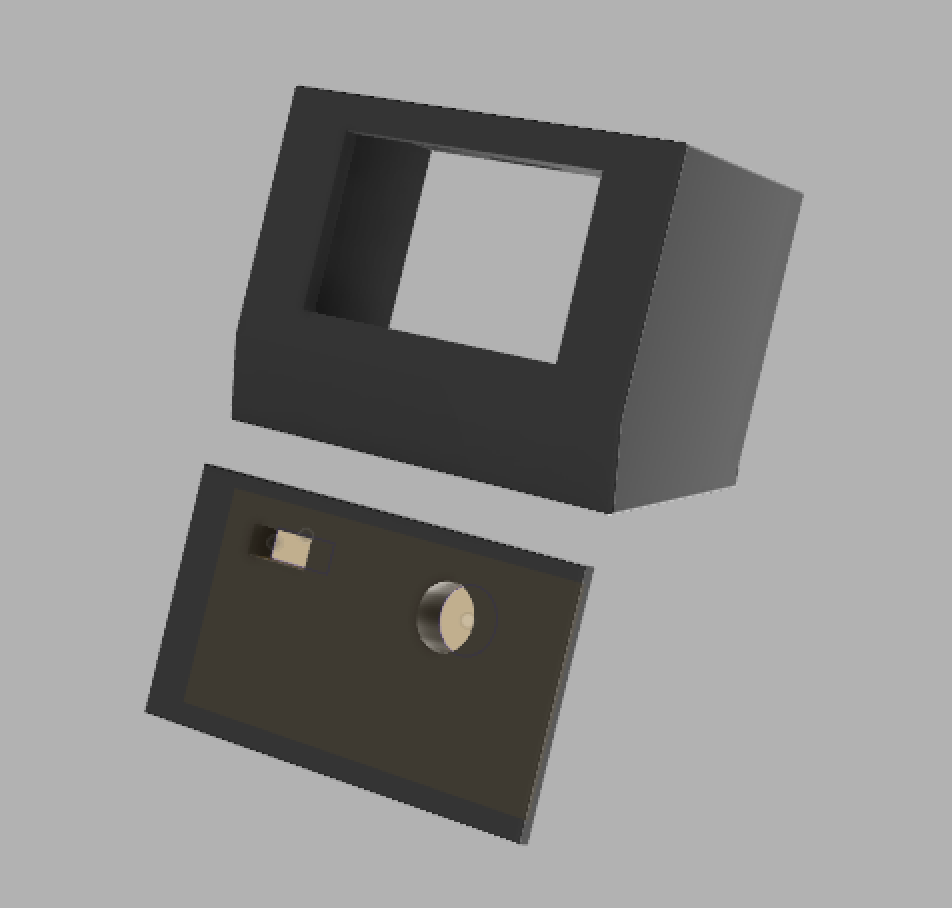
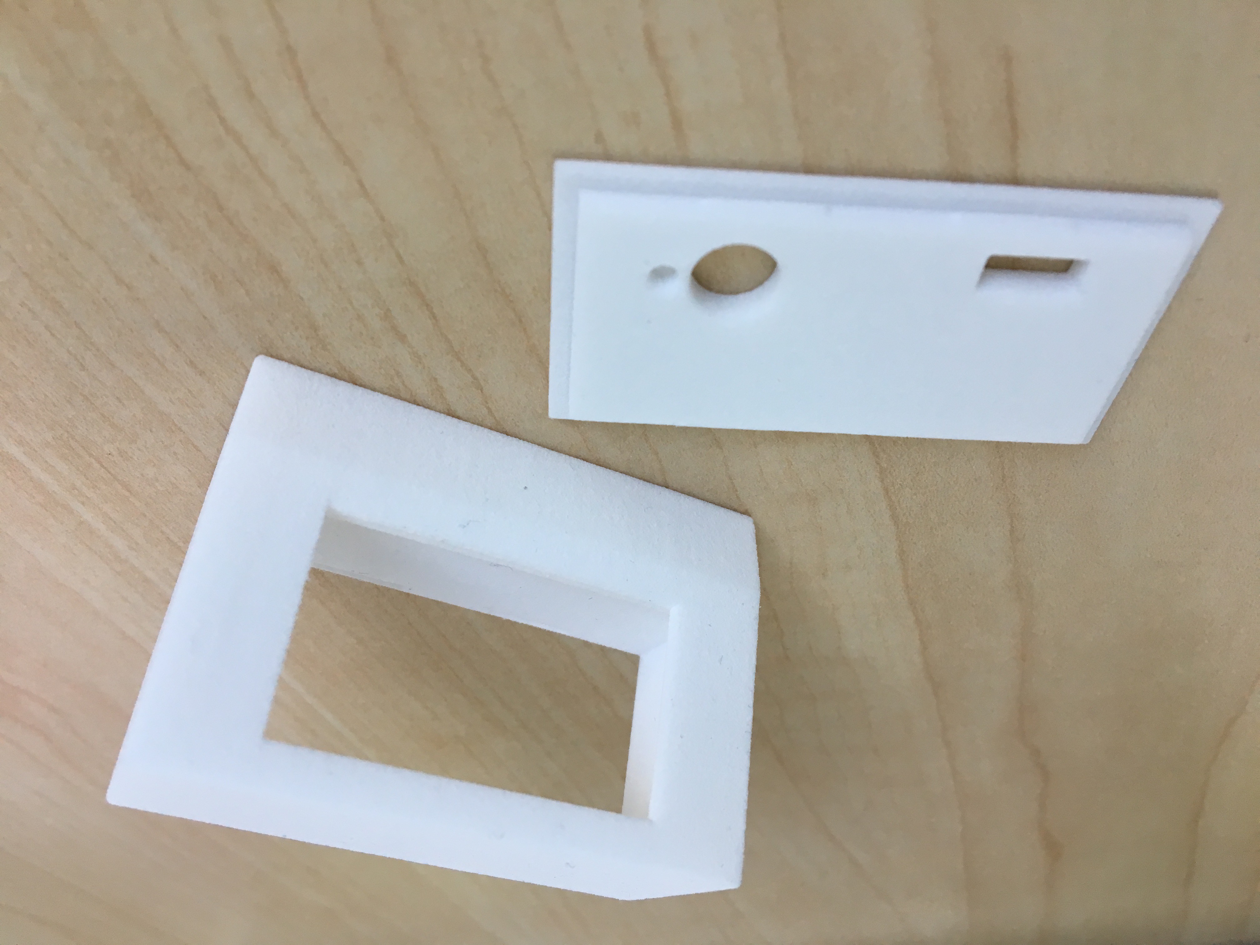
print from Shapeways
The summer of 2016 was dedicated to enclosures. My friend Marc introduced me to Fusion 360(5), and with his guidance I was on my path to designing a real enclosure for the clock. While previously I had cut some holes in boxes before, this was the first time I specified the shape of the enclosure for a project I was building. Months later friends and family asked about the similarity to the original 128k Mac. While I didn't consider it at the time, I must have subconsciously been influenced by this classic design. I suspect it must be the angled-back profile that is so iconic; welcoming and approachable. I feel it encourages a certain posture on the desk, and I hope my little clock echoes that historic product.
Fusion 360 has a steep learning curve, so I am thankful for the tutelage of Marc. We even attended a meetup at the Autodesk HQ at some point IIRC. I recall the allowances for the back panel fitup being particularly challenging, especially the small tabs that lock it in to place. Despite the challenges, I think the choice to build a 3D printed enclosure defined the DC-002, and was well worth the effort.
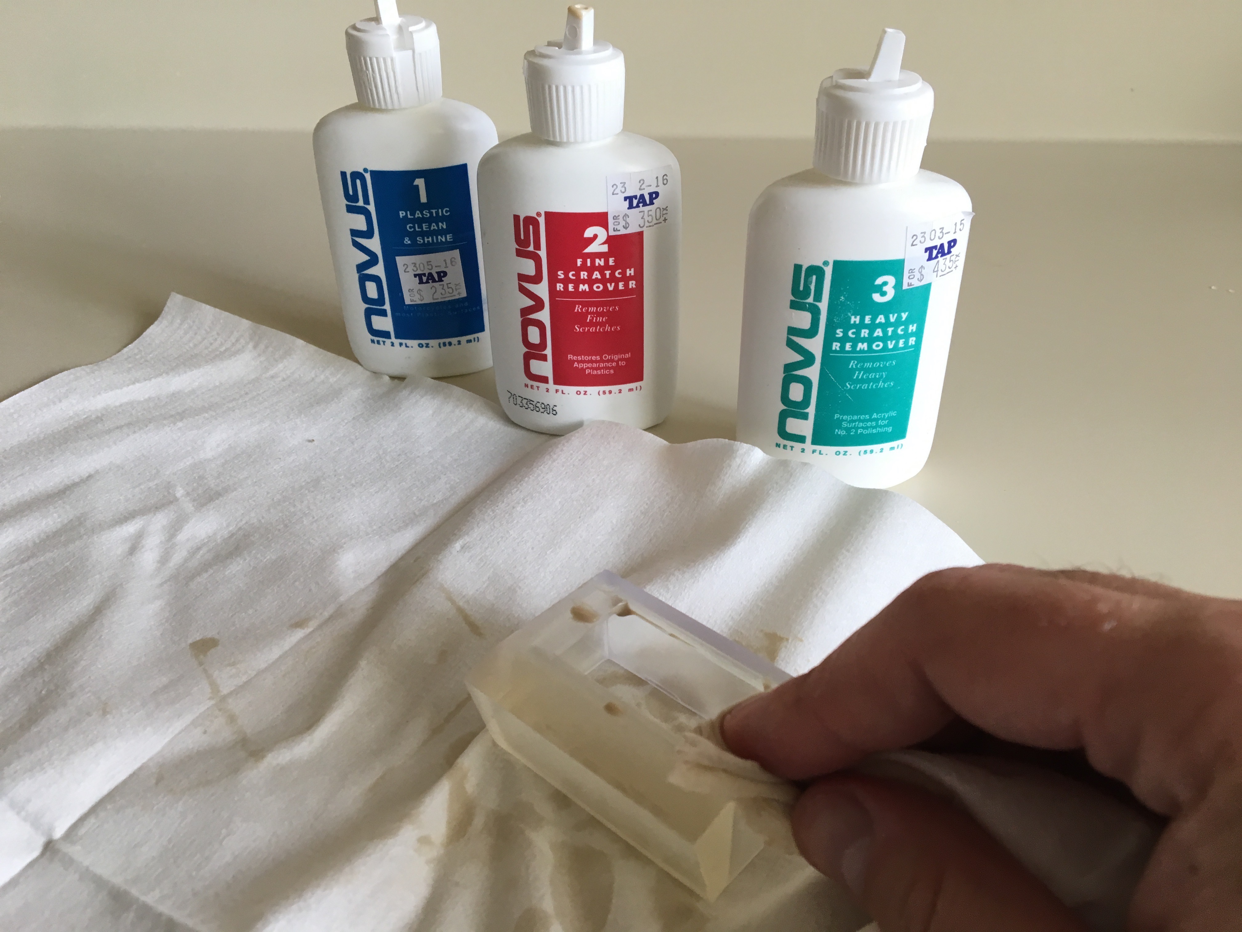
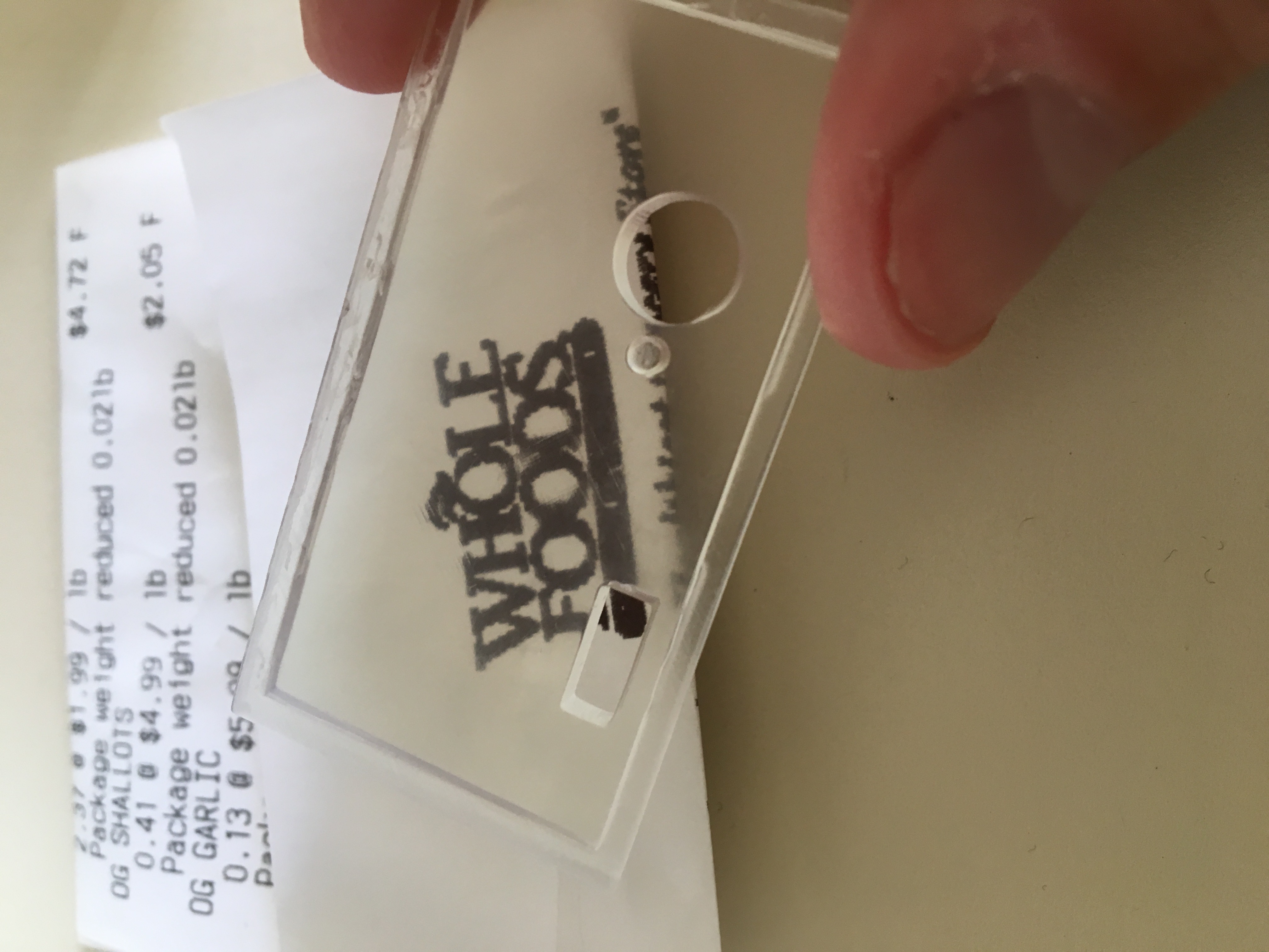
Ordering from Shapeways was straightforward, and it only took me two tries to get a case that worked. The cheapest option "strong versatile plastic" seemed like the best option at the time, and I've been pleased with the result. Marc also printed a clear version on his Form 1 3D printer. It required a bunch of additional finishing work to make optically clear, but with enough application of NOVUS plastic polish, it turned out great. Again the clear version reminds me of some prototypes I've seen around the internet…
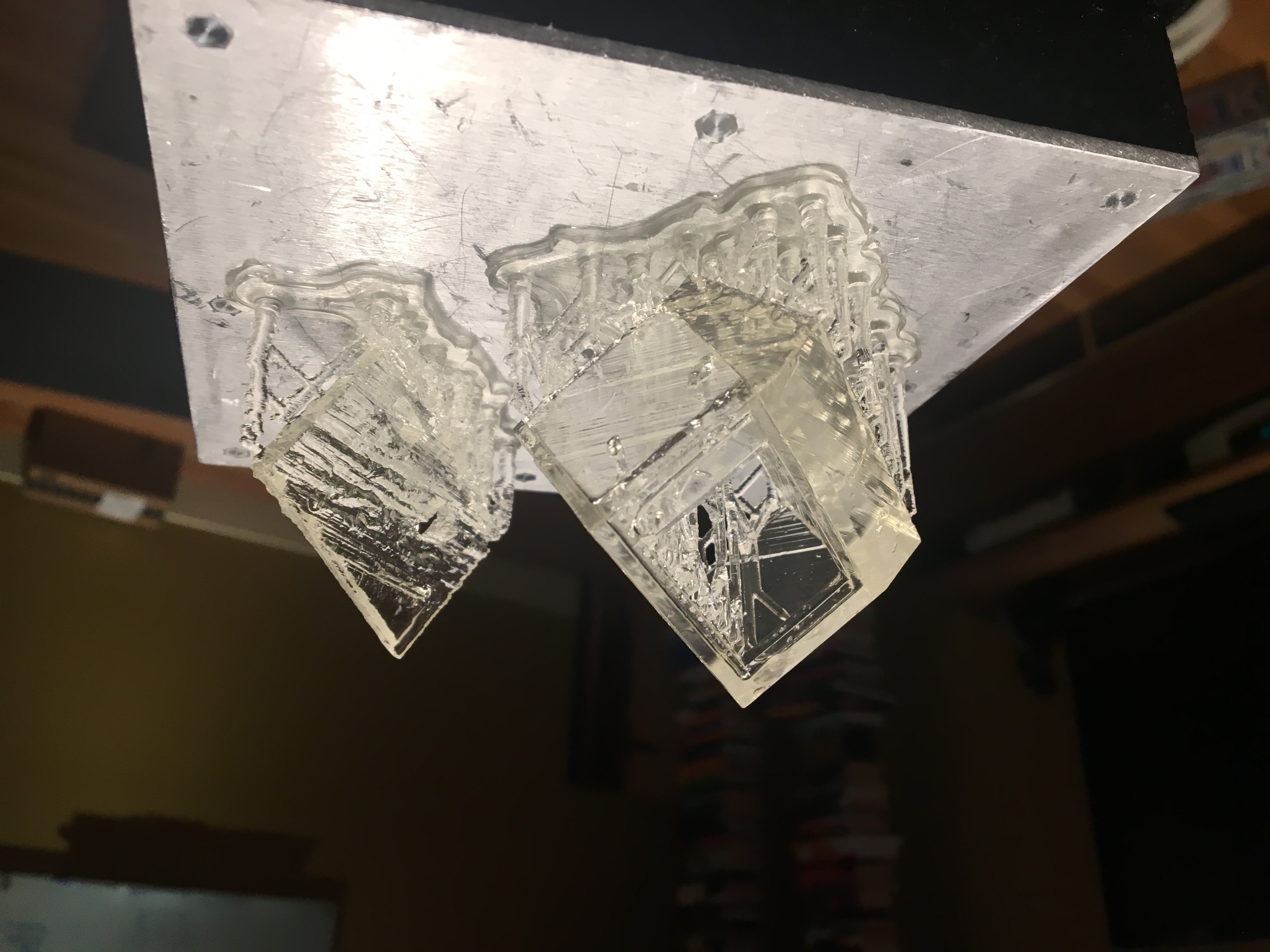
optical clarity demonstration, and assembled clear DC-002.
Deadline and Finishing the Production Run
By August, 2016 I had to complete the first DC-002 unit in time for a wedding gift. An excellent motivation, but the immovable date didn't allow enough time for me to complete appropriate packaging. I cobbled together a box and some tissue paper for the first one—but this experience made me start thinking about what it would take to make really satisfying packaging, and changing the perception from a craft project into a product.
I let the remaining units burn-in for several months. This surprisingly actually resulted in one failing unit (I was mostly just procrastinating and didn't think I was doing a real burn-in test). My attempts at rework ended up destroying the board. It's hard to recall all the details of debugging so many years removed from the particular incident, but I have notes indicating that the unit with serial number #005 that appears to have had incorrectly configured fuses such that JTAGEN was enabled, making the pin I had used for clock input from the DS3231 unavailable. I must have reworked the board enough times to lift a pad or something—so I ended up ordering 3 more PCBs, allowing me to increase the production run from 6 to 8 units.
Packaging
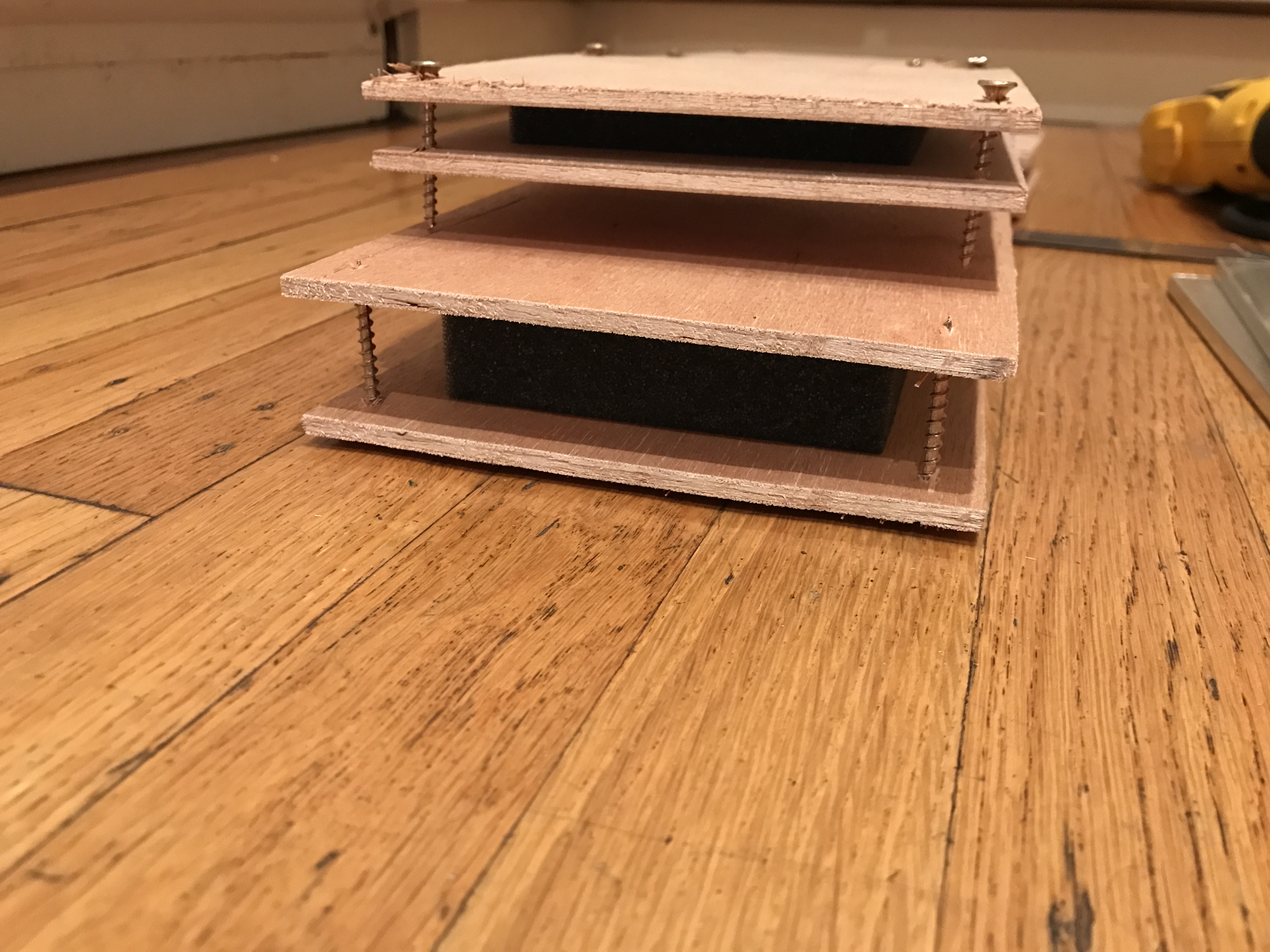
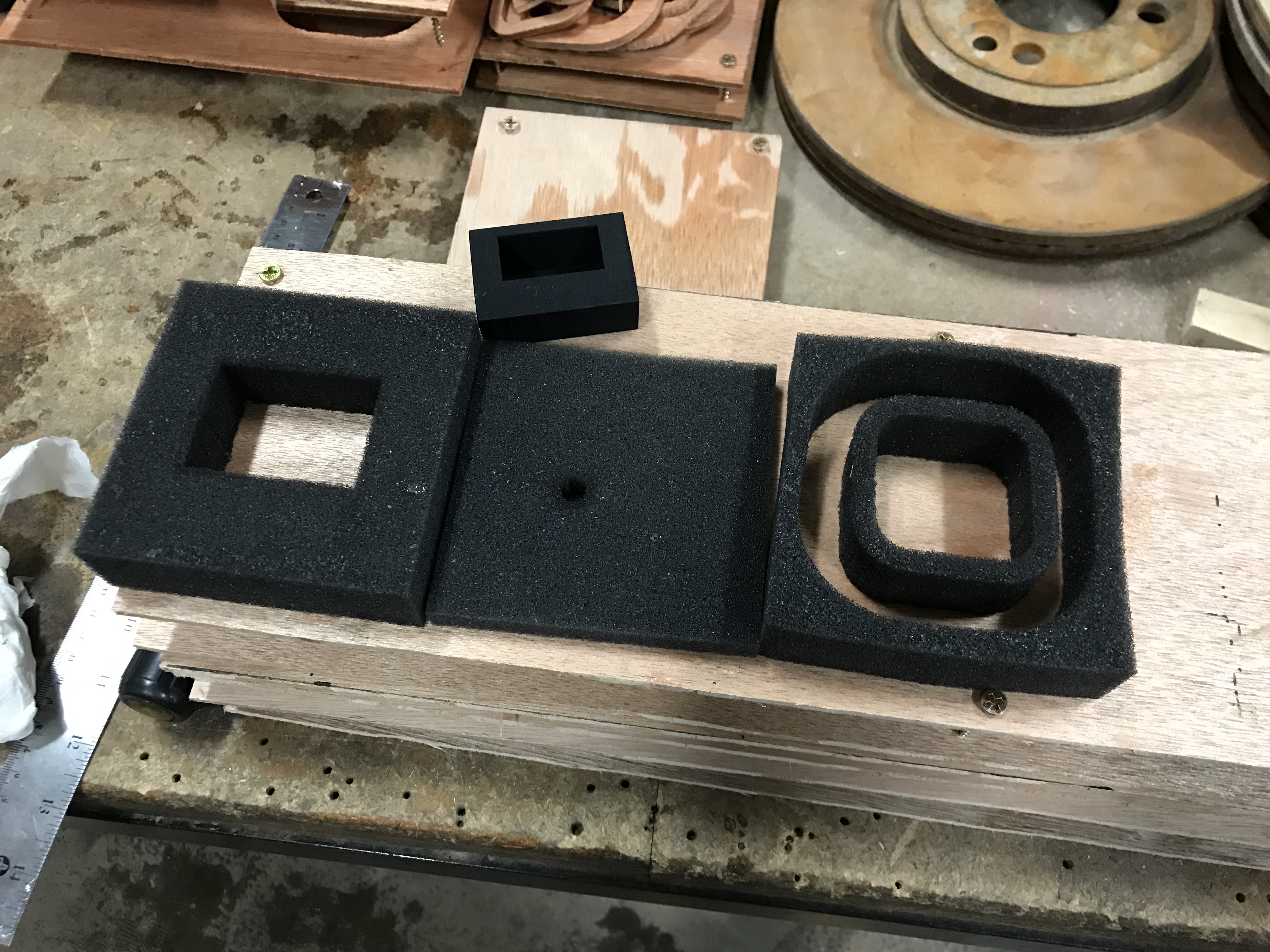
As I had been frustrated with initial packaging, I started investigating foam with pockets cutout for the clock and accessories. I was able to source some suitable ½" and 1" foam sheets locally from the extremely helpful Cushion Works. After a visit to the shop to understand the options, I ordered sheets of charcoal colored "ELEC" foam, which I believe is polyurethane based closed-cell foam. I had designed a series of 2D cut pieces with spaces hollowed out for the clock, power adapter, and cable. The layers were stacked up to form a 4" cube and inserted in to the box in 3 foam assemblies achieved by gluing some of the layers together with spray adhesive. The 4" square layers were stacked as follows:
1) 1/2” thick square uncut
2) 1” thick square with hole cut for clock
3) 1/2” thick square with hole cut for knob
4) 1/2” thick square uncut
5) 1” thick square with concentric holes cut for power adapter and USB cable
6) 1/2” thick square uncut

Layers 2-3-4 and 5-6 are bonded with adhesive.
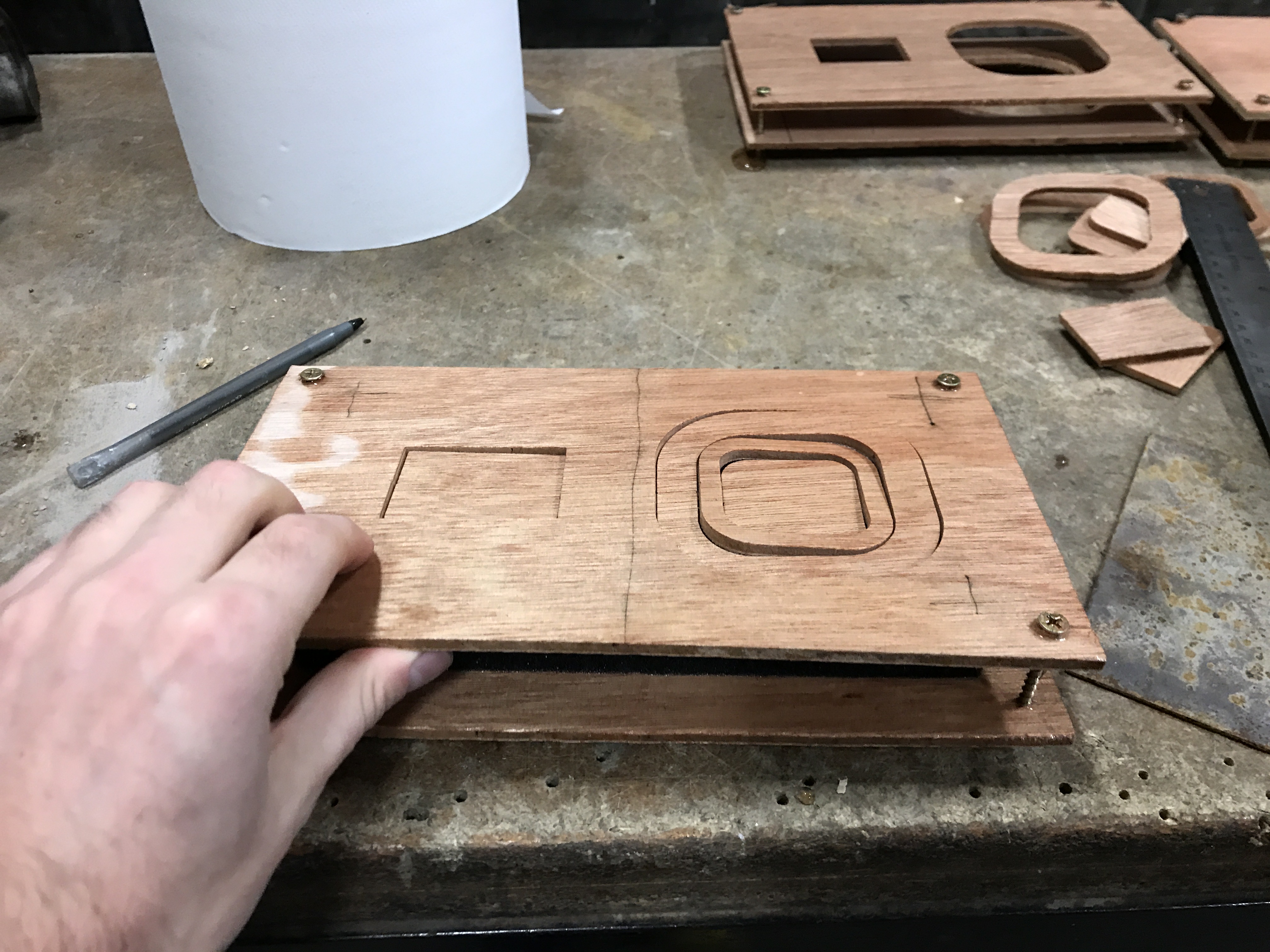
Now I just needed to figure out how to make these intricately cut pieces. Because polyurethane can't safely be cut with a hot wire cutter, I was led on the adventurous sidequest of learning how to cut it the pieces I needed with a waterjet cutter.
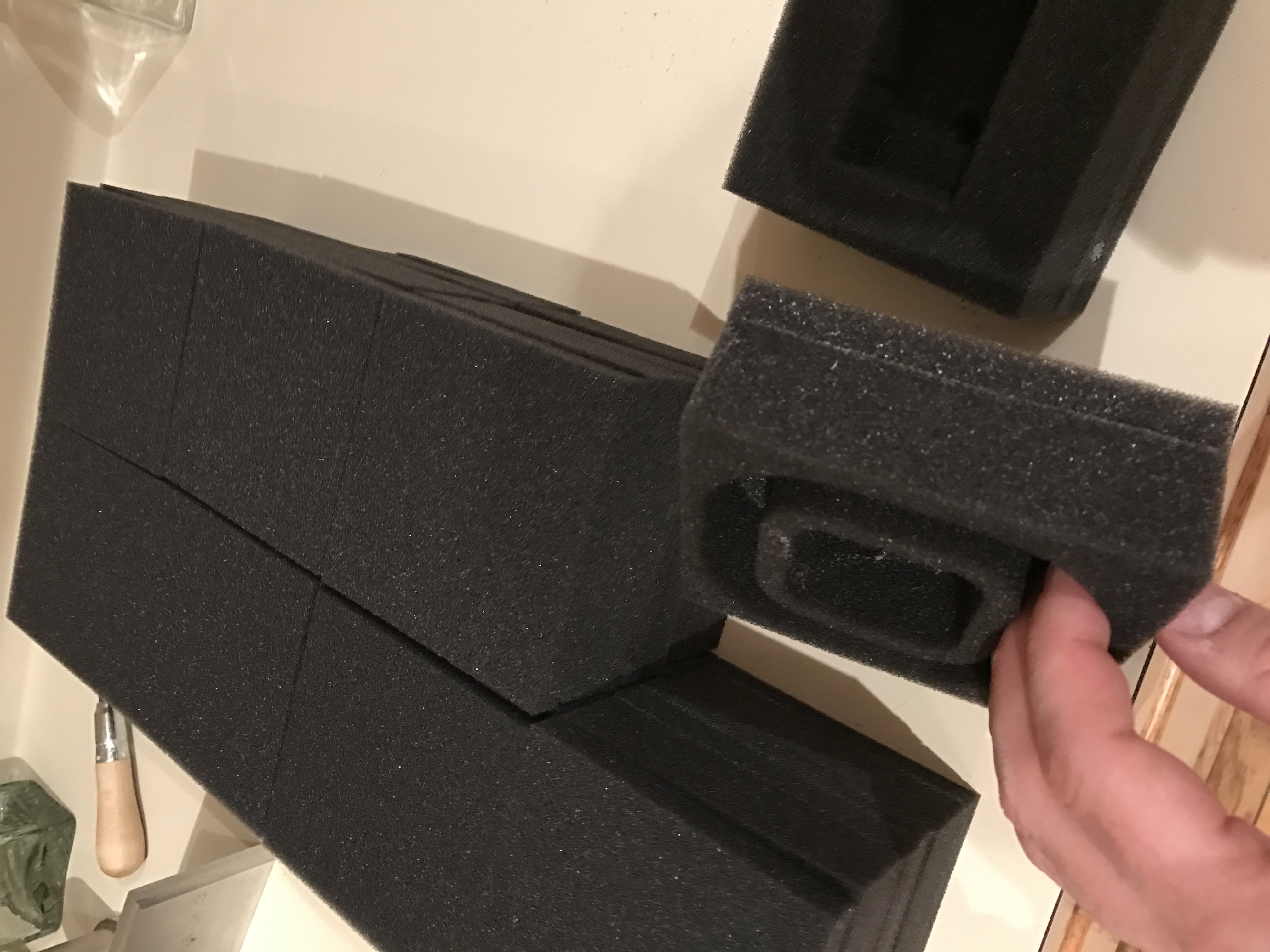
Waterjet foam cutting
So after a short run on the waterjet, all of the pieces were cut and ready for packing.
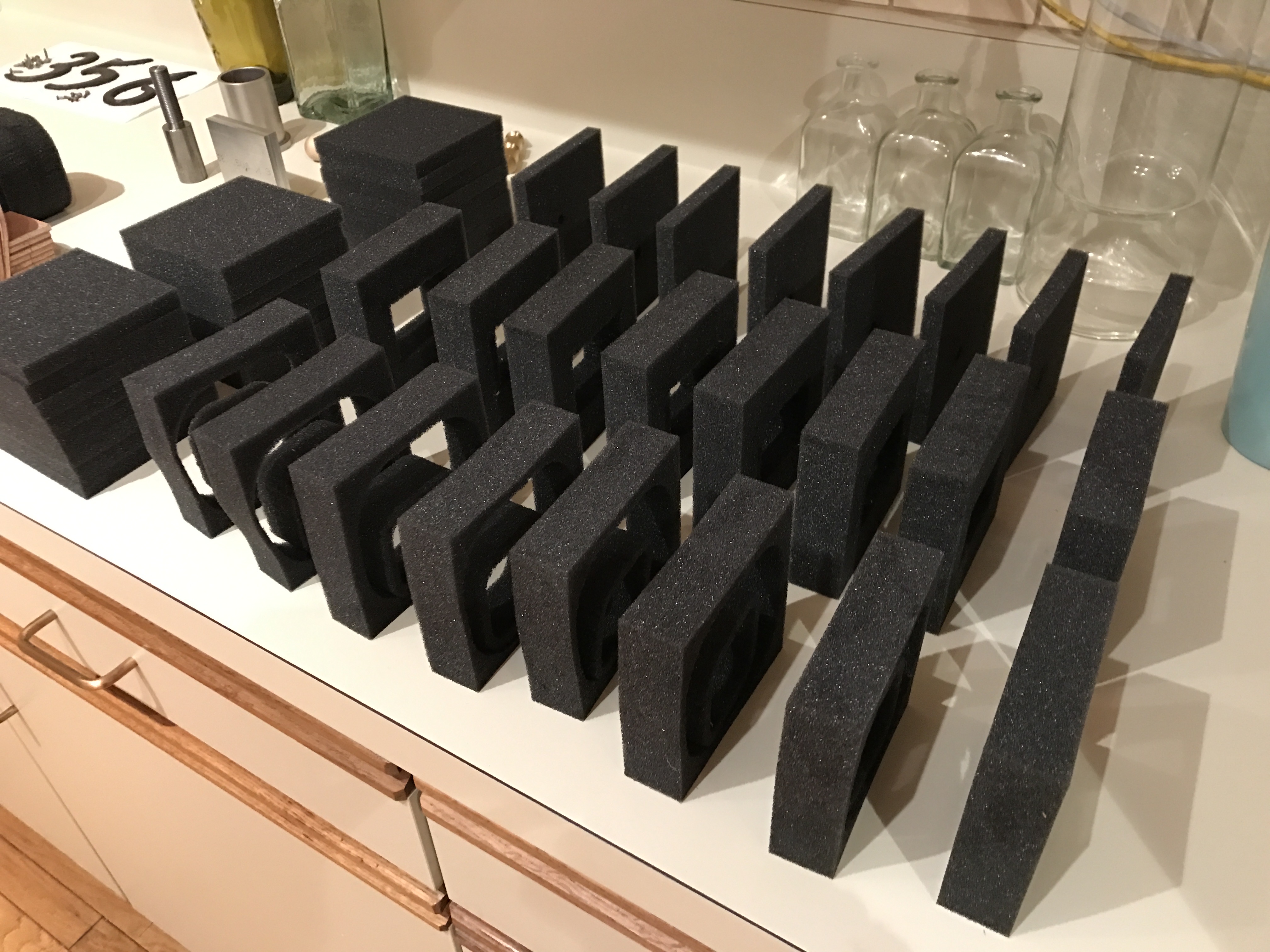
waterjet cut foam pieces.
Manual

Cost
I had intended to do a cost analysis of the entire project with detailed spreadsheets and specific line-items for each expense, but some of the accounting has been lost to time. I think a high-level summary might be fair to indicate the cost was higher than estimated at the beginning of the project, and unit-cost was above what the market would have supported. It's hard to account for things like training on the waterjet machine at TechShop, because it was so much more valuable as a personal experience than it was for completing this project. Overall, worth every penny.
Conclusion
Finally for Christmas 2016 I delivered all of the remaining DC-002 units as gifts to friends and family. It was extremely satisfying to craft something nice for the people I love, and endless fun to build them. For the sixth anniversary of the project, I've finally been able to publish this write up with the hope it'll inspire some folks to go out and build joyful things, and maybe help someone get unstuck with some weird technical problem.
The Python script that syncs the DC-002 to a computer has been updated for Python 3 in preparation for publication. During the update, I found that after 6 years my personal clock had only drifted by about 3 minutes.
If you end up building something similar or taking any inspiration from my work here, please reach out, I'd love to hear about it.
The current release is software version 1.1.1; HW version 1.2b.
Resources
- Download User Manual
- Clone SW & HW Source from GitHub
- Download BOM from GitHub
- Check out Schematic & PCB Layout at Upverter
- Buy PCBs from OSH Park
- Buy Solder Stencil from OSH Stencils
- Buy Enclosure from Shapeways
- Buy Enclosure Back Panel from Shapeways
Notes
- And maybe 6 more years to document it…
- For the past couple of years I've used exclusively KiCAD, and would strongly recommend it over a web-based product.
- I've since assembed a Whizoo reflow oven kit, and it's awesome. Highly recommended; I painted mine Tektronix blue.
- I've mostly switched over to lead-free now and it isn't that big of a deal, but I still occasionally find lead solder necessary for repairs and other hobby uses. OSHA has a lot of information about the risks.
- It seems like the licensing options for personal use aren't as great anymore, but I haven't used Fusion 360 much recently.
- Sadly, TechShop abruptly shuttered all of their locations about 6 months later. I also took my first welding class at TechShop in 2008. They'll be missed!